

Appearance
Flux Core ESC Rev A — Integration
Assembly
The Flux Core is a castellated module — it solders directly onto a compatible power stage PCB. It has no mounting holes of its own. Align the module to the power stage footprint and reflow or hand-solder all castellated pads.
Pinout
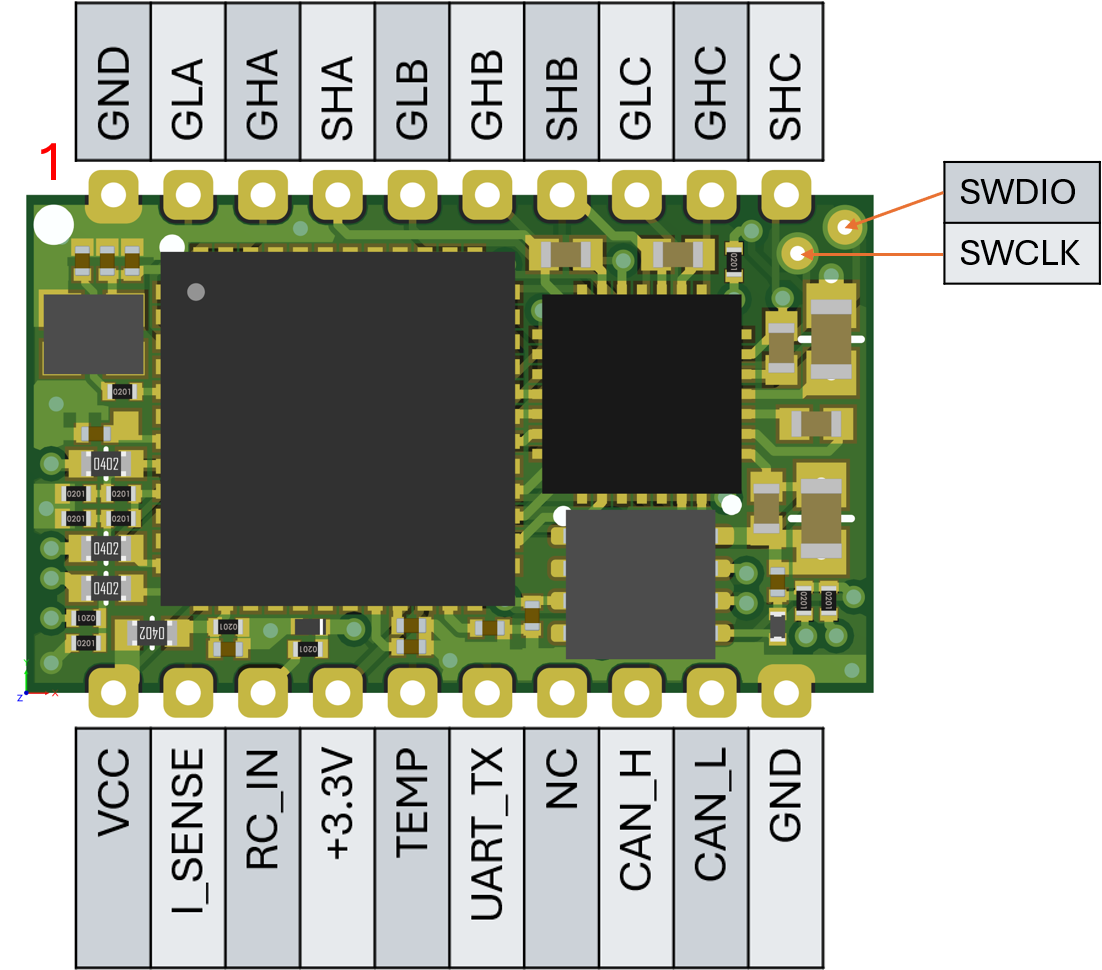
Top Edge (left to right)
| Pad | Description |
|---|---|
| GND | Ground |
| GLA | Gate drive — Phase A low-side MOSFET |
| GHA | Gate drive — Phase A high-side MOSFET |
| SHA | Phase A sense (half-bridge output to motor) |
| GLB | Gate drive — Phase B low-side MOSFET |
| GHB | Gate drive — Phase B high-side MOSFET |
| SHB | Phase B sense |
| GLC | Gate drive — Phase C low-side MOSFET |
| GHC | Gate drive — Phase C high-side MOSFET |
| SHC | Phase C sense |
Bottom Edge (left to right)
| Pad | Description |
|---|---|
| VCC | Full battery voltage from power stage — used for voltage sensing |
| I_SENSE | Analog current sense from shunt resistor amplifier on power stage. [Needs information about gain] |
| RC_IN | +5V tolerant PWM or DSHOT input — use when not controlling via CAN |
| +3.3 V | +3.3V input supply |
| TEMP | Optional remote temperature sensor analog input from power stage |
| UART_TX | Serial telemetry output (AM32 responds to DSHOT telemetry requests) |
| NC | Not currently used |
| CAN_H | CAN FD differential high |
| CAN_L | CAN FD differential low |
| GND | Ground |
Bottom Face (exposed pads, not castellated)
| Pad | Description |
|---|---|
| SWDIO | SWD data — MCU programming and debug |
| SWCLK | SWD clock — MCU programming and debug |
| RESET | Reset pin — MCU programming and debug |
| BOOT0 | Boot0 — MCU programming and debug |
| +3.3V | Input power for MCU |
| GND | Ground |
SWD access: SWDIO and SWCLK are exposed on the underside of the module and on two pads in the top right corner. Once soldered, only the smaller top pads are accessible. The module ships preloaded with the AM32 bootloader — in-field firmware updates are performed over CAN.
Phase order: Phases C and A are deliberately swapped on the PCB for layout efficiency. The firmware accounts for this — no external correction is needed.
CAN FD Bus
Connect CAN_H and CAN_L to the CAN bus. Integrators must decide how to terminate the bus for their own application. Future revisions may enable mcu-driven termination on this module.
CAN Setup
The module ships preloaded with AM32 firmware (custom build supporting both CAN FD and DSHOT/PWM simultaneously). To use CAN control:
- Before soldering, optionally flash the latest firmware over SWD using an ST-LINK or J-Link probe
- Set a unique
CANID(1–127) for each ESC on the bus — see Parameters - Set
CAN_SPEEDto match the bus baud rate - Send throttle commands using the AM32 CAN protocol
See the AM32 project documentation for the full CAN message format, node configuration, and configurator tool.
DSHOT/PWM via RC_IN is also supported on the same firmware build and is auto-detected alongside CAN.