

Appearance
RPI-Zero M.2 E-Key Backpack — Integration
Assembly
The backpack mounts directly to the back of an RPi Zero 2 using pogo pins for both power and data connectivity. No soldering is required if using pogo pins. For permanent installations, secure the backpack with standoffs aligned to the RPi Zero mounting holes.
Pogo Pin Installation
Install 2.0mm diameter spring-loaded pogo pins (minimum 6mm height) into the circular pads on the back of the backpack labeled for USB, GND, and 5V. These pins align with the matching pads on the RPi Zero, allowing the boards to be mounted back-to-back and secured with standoffs.
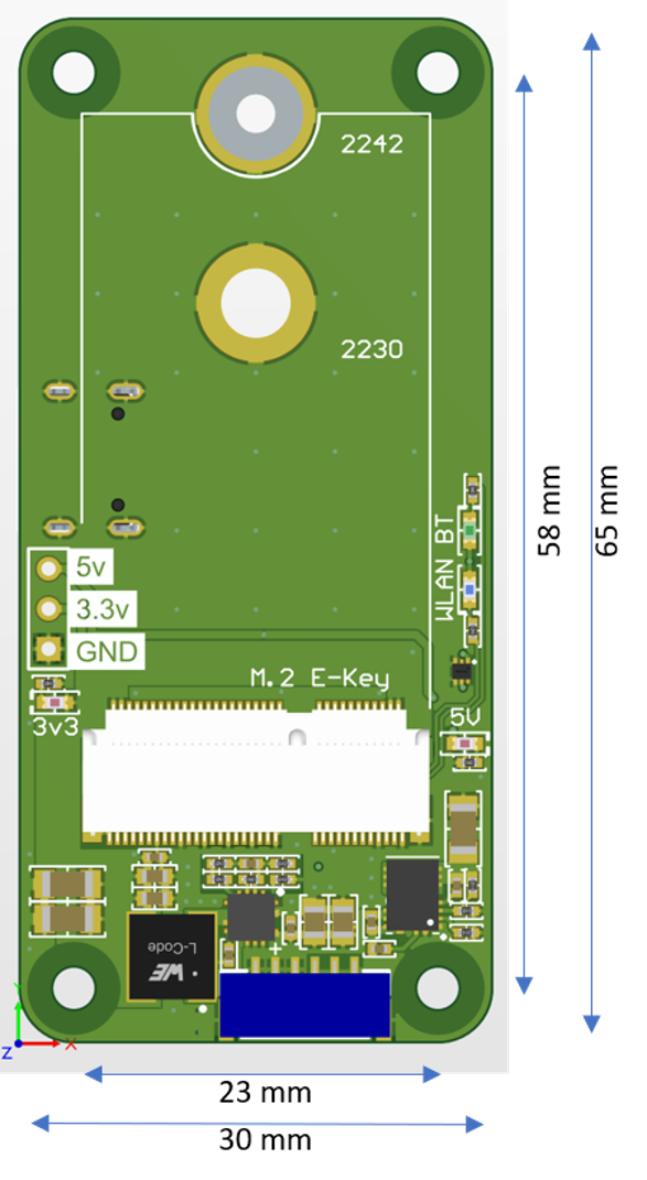
Power Connector Pinout
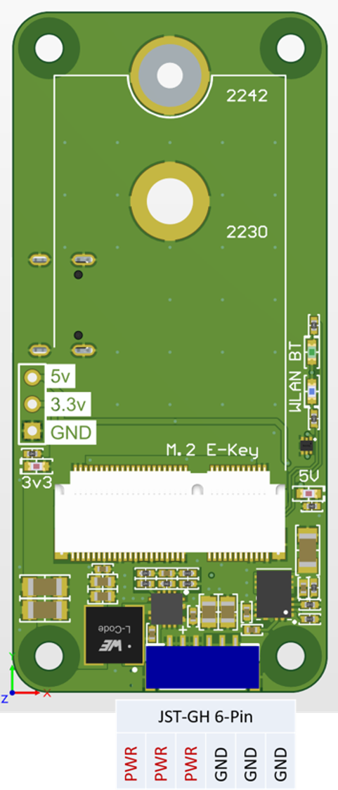
We recommend using all the pins for power and ground to ensure proper operation under high loads or vibration environments.
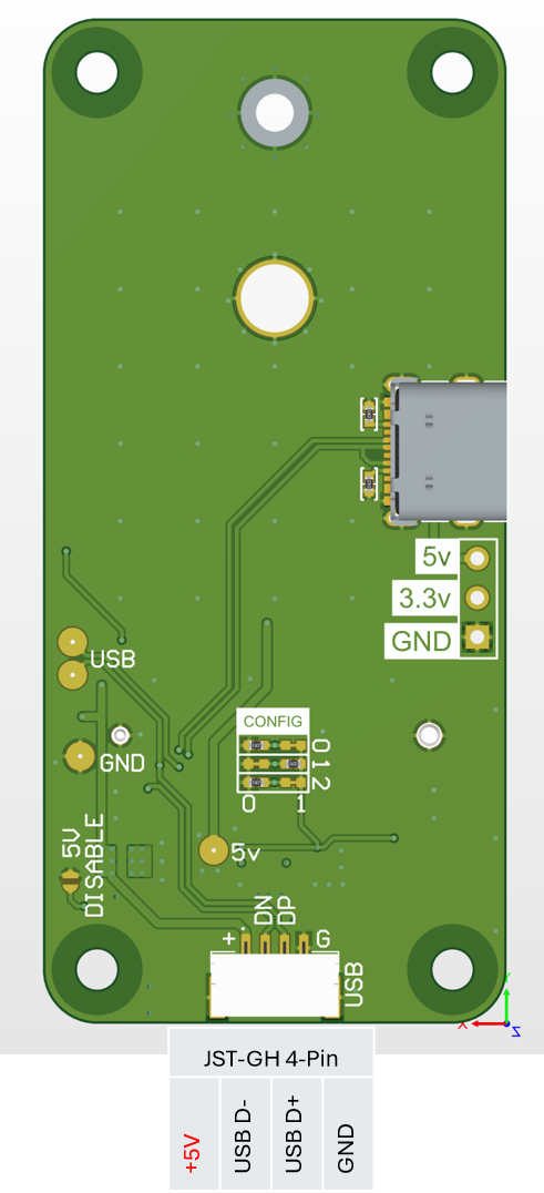
The USB 2.0 data lines are connected from the M.2 E-Key connector to both the 4 pin JST-GH connector and USB-C connector. Only use one at a time as they are the same signals.
Adding Pogo Pins
The circular pads on the back labeled for USB, GND, and 5V are sized for 2.0mm diameter standard spring pin (Pogo) contacts, recommended at least 6mm height. They are positioned to align with the matching pads on the RPI Zero 2 W allowing the two boards to be mounted back-to-back with stand-offs to reduce wire count. It is recommended to use the 6-pin JST-GH power connector as the only input, as the 5V regulator is sized to power both the M.2 card and the RPI Zero.